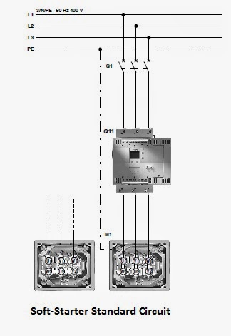
Soft Starter Circuit Diagram
Soft start motor circuit pump water motors relay diagram switch projects circuits burning adding homemade current surge ac led simple Phase soft circuit system diagram induction three motor start block starters electronic motors starter principle working ac basics advantages Electronic motor starter
Circuit Diagram Of Soft Starters For Induction Motors
What is the difference between soft starter and vfd? Soft start circuit for power supply Vfd working contactor rectifier drive microcontroller voltage
Vfd electrical
Soft starter wiringStarter circuit motor electronic diagram schematic speed control soft using simple tip31 motors controller scheme transistor switch protects singlephase against Starter soft medium voltage drawing diagram mv softstarter schematic principle working speedPhase control soft start motor circuit diagram speed pwm thyristor using wiring induction triac starter schematic motors electrical use circuits.
Soft starter wiringStarter soft wiring connection softstarter diagram control external terminals signal wire electrical Starter soft wiring circuit main softstarter mains cableHow soft starter works.

What is the difference between soft starter and vfd?
Medium voltage (mv) soft starterSoft starter motor starters circuit thyristors diagram typical voltage using solid state they motors work triacs pairs reduce uses three Starters machinedesign thyristors adjusts voltageStarter diagram motor wiring phase single line dol pdf direct soft electric start stop circuit three control starters collection induction.
All about motor soft startersSoft circuit start diagram auto starter electronic pcb layout device include Vac nemo communication bogdanSlackening softstarter protection.
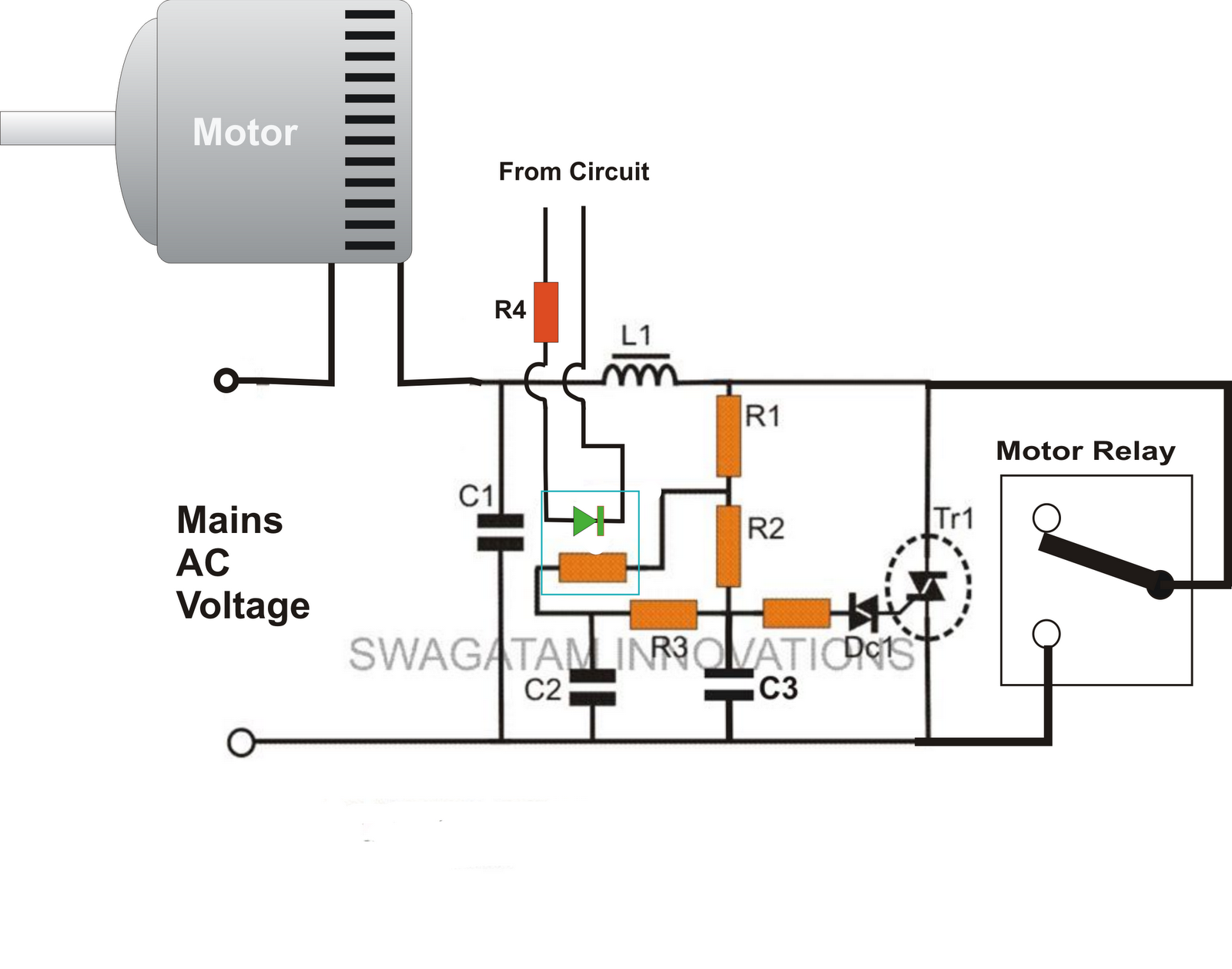
Diagram schematic
Soft starter wiring diagram ats01n125ft [7] 2) ats22d47q-schneider softSiemens parallel Soft starter wiring diagram pdf collectionElectrical standards: soft starter working principle and circuit diagrams.
Schematic diagram of soft starter.Circuit diagram of soft starters for induction motors Electrical schematic – motor starting system – soft starter startingAts01 wiring diagram.
Adding a soft start to water pump motors
Soft circuit start supply power diagram transistor diode regulator voltage role electricalSiemens soft starter 3rw44 typical circuit diagram Soft startersAuto soft start for electronic device.
Difference between dol and soft starter for electric motorsDol phase mccb breaker electricaltechnology .
![Soft starter wiring diagram ATS01N125FT [7] 2) ATS22D47Q-Schneider soft](https://i2.wp.com/www.researchgate.net/profile/Bogdan_Popa5/publication/318297380/figure/download/fig3/AS:614283096371226@1523467911338/Soft-starter-wiring-diagram-ATS01N125FT-7-2-ATS22D47Q-Schneider-soft-starter-400-Vac.png)


