3 Phase Motor Controller Schematic
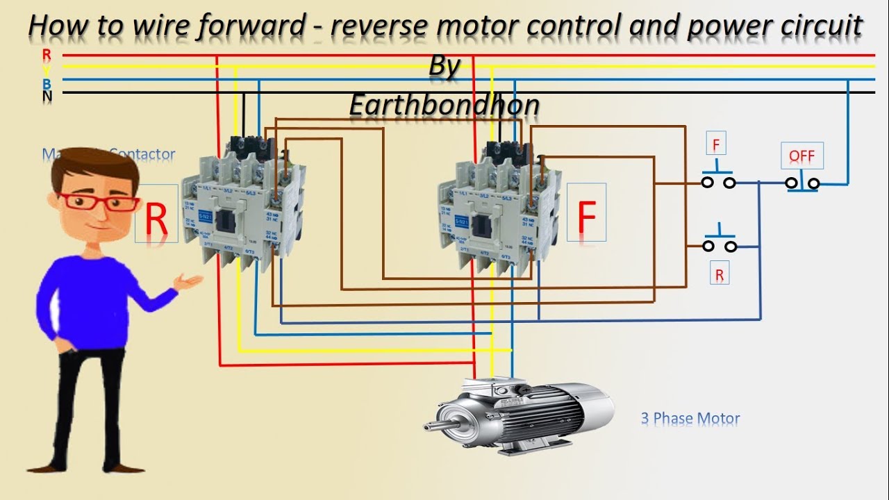
3 phase induction motor speed controller circuit ~ electronic circuit Forward & reverse 3 phase ac motor control circuit diagram Forward reverse motor diagram control phase wiring contactor electrical starter three wire controlling contactors cont online vac shown come had
11+ Three Phase Motor Control Circuit Diagram | Robhosking Diagram
Forward reverse motor control diagram for 3 phase motor Motor phase speed induction circuit controller circuits diagram pwm three electronic ic ac homemade arduino brushless triac using regulator input Brushless dc motor controller using arduino and ir2101
Circuits system plc
Motor diagram phase wiring three controller control circuit lathe needed figure help machinist hobbyBldc motor controller: design principles & circuit examples Bldc pwm brushless wiring inputsController factor.
3 phase motor control circuit diagram pdfHow a 3 phase motor control circuit works Diagram motor phase wiring forward circuit control schematic starter reverse ac motors stop start induction electrical pdf diagrams winding mainController brushless schematic motor 36v circuit esc dc schematics phase hall sensor board basic eagle arduino make used 3phase motors.

3 phase motor control panel wiring diagram
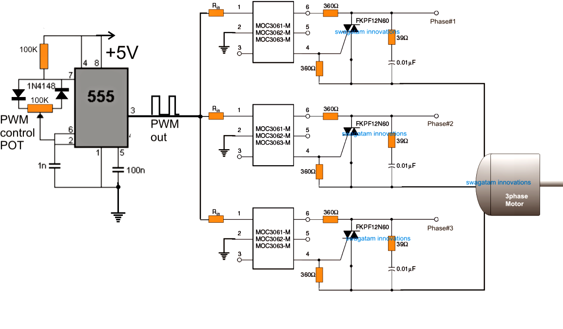
3 phase dc motor controlSchematic controller brushless hall motor sensor control phase dc chip circuit esc three schematics motors simple converter 3 phase ac motor speed control – electronic circuit diagram“3 phase brushless dc motor” “3 phase brushless dc motor controller.
3 phase ac motor controller3 phase motor control circuit diagram Motor circuit control diagram wiring simple latching contactor switch diagrams contact instrumentation auxiliary float previous next instrumentationtools toolsBldc motor controller circuit phase three hall voltage sensors current.

Motor phase dc control
Motor ac circuit phase control speed schematic diagram 2009 circuits three gr click next controlling controller june11+ three phase motor control circuit diagram Troubleshooting three basic hardwired control circuits used in startingRev / for three-phase motor connection power and control diagrams.
Figure 7-13.control circuit components.3 phase motor programmable controller 12+ 3 phase motor control circuitPhase induction principle wiring electrical basics vfd compressor timer motors advantages torque.

Motor control wiring diagram
Motor control three starter phase circuits electric starting autotransformer basic circuit electrical troubleshooting time after used hardwired typical voltage mainMotor control phase connection three diagram rev wiring power electrical delta diagrams circuit star reverse forward installation thermal overload symbol Motor circuit phase diagram control rigWire reversing contactor.
Motor arduino controller brushless dc ir2110 bldc circuit using simple esc diy speed back terminals note code sensorless grounded connectedThree phase motor control circuit diagram pdf Brake seekic“3 phase brushless dc motor” “3 phase brushless dc motor controller.
Phase motor controller programmable circuit diagram fig diy electronics electronicsforu off project projects
Motor ac diagram phase wiring controller magnetek century electronics forward reverse motors labMotor phase circuit control 3 phase motor control circuit diagramHow 3 phase motor control circuit works.
Bldc motor control circuit diagram datasheetPhase motor control diagram Phase schematic circuits phases 3s wires fuse supply wye11+ three phase motor control circuit diagram.


